nest Hello Wiring Diagram, Nest Hello Advanced Wiring Diagram, 6.25 MB, 04:33, 63,749, gt8monster, 2018-06-16T10:14:46.000000Z, 19, Nest Hello Doorbell: 18 Questions/Answers You Need To Know - Smart Home Point, www.smarthomepoint.com, 1057 x 852, png, nest diagram hello doorbell wiring google camera chimes chime install multiple lh4 googleusercontent answers questions know need pre, 20, %ef%bb%bfnest-hello-wiring-diagram, Anime Arts
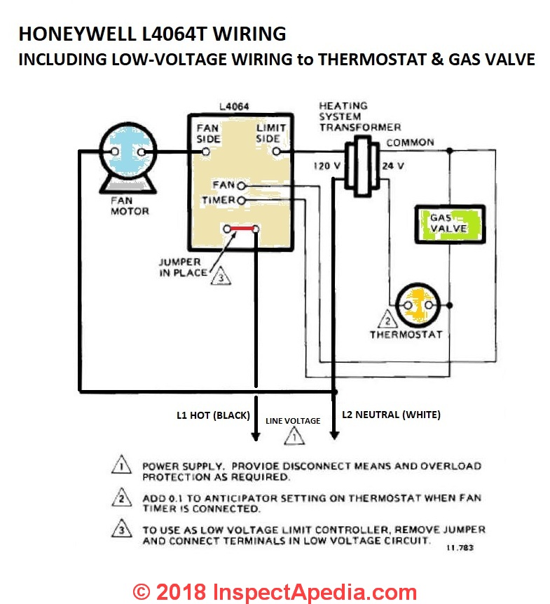
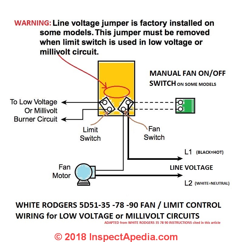
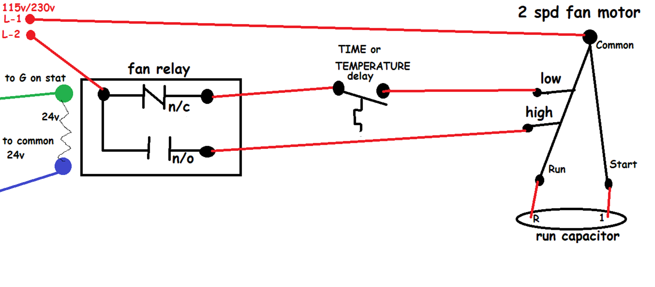
This one explains the 2 ways this switch can be wired. Furnace fan limit switch wiring diagram wiring diagram is a simplified tolerable pictorial representation of an electrical circuit it shows the components of the circuit as simplified shapes and the power and signal connections amongst the devices. Sep 18, 2008, 06:38 am. Remove the wires attached to the old fan/limit control.
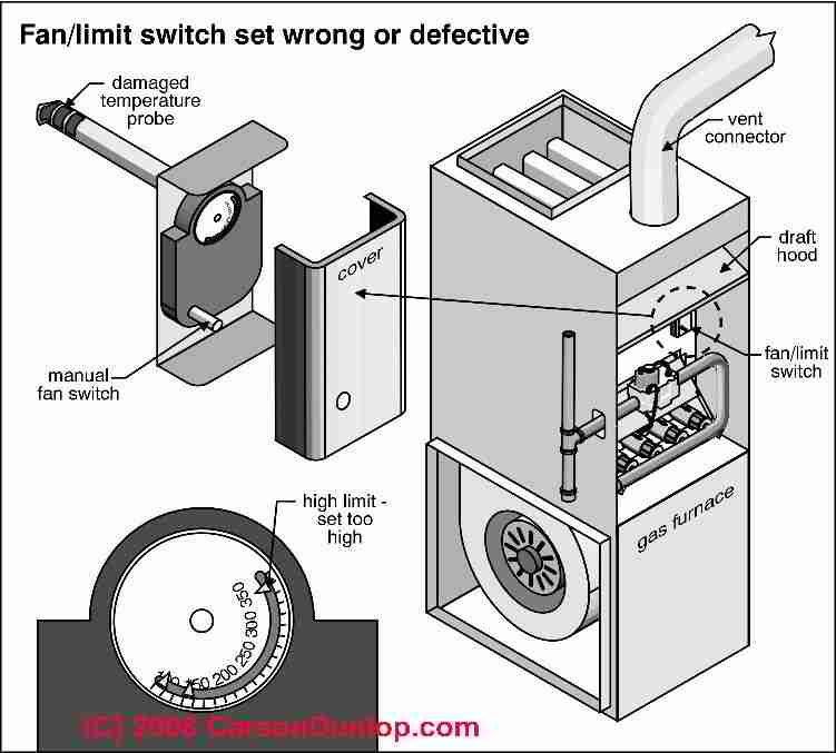
Ok i read a little on the fanlimit control concept. Dual cooling fan wiring diagram electric cooling fan radiator fan automotive electrical. As the air in the furnace plenum warms up the bimetallic spring expands turning a gear. The following is a wiring diagram for a honeywell fan limit switch control. Before beginning any wiring make sure you turn the power off. Turn the power off at the furnace and go a step further for safety and turn the power off at the breaker. The furnace fan limit switch is located within the furnace panel cover, typically in the upper right corner, from where it controls the operation of the furnace blower. If the fan does not go off, then its a problem with fan limit switch inside the look on the wiring diagram glued to the inside cover of the furnace. Male flag connectors on both the fan and limit switches (fig.
How to Install & Wire the Fan & Limit Controls on Furnaces Honeywell L4064B & All White Rodgers
How to Install & Wire the Fan & Limit Controls on Furnaces Honeywell L4064B & All White Rodgers

Honeywell Furnace Temperature Fan Limit Switch Control - Heating

How to Install & Wire the Fan & Limit Controls on Furnaces Honeywell L4064B & All White Rodgers

[DIAGRAM] Furnace Fan Limit Control Wiring Diagram FULL Version HD Quality Wiring Diagram
Honeywell Fan Limit Switch Wiring Diagram | Wiring Diagram

How to Install & Wire the Fan & Limit Controls on Furnaces Honeywell L4064B & All White Rodgers

Honeywell Fan Limit Switch Wiring Diagram | Free Wiring Diagram

Honeywell Fan Limit Switch Wiring Diagram | Fuse Box And Wiring Diagram

35 Honeywell Fan Limit Switch Wiring Diagram - Wire Diagram Source Information
